Stainless Reducer
A stainless steel reducer is a pipe fitting that changes the diameter of a pipe, allowing for connections between pipes of different sizes.
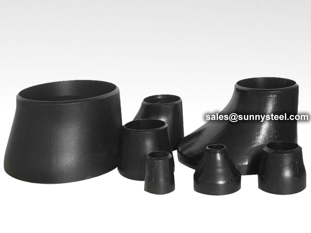
Pipe Reducers are the component in a pipeline that reduces the pipe size from a larger to a smaller bore (inner diameter).
A steel pipe reducer is a component used in the pipelines to reduce its size from large to small bore in accordance to the inner diameter.
| Nominal pipe | Outside Diameter at Bevel | Center to End | |||
|---|---|---|---|---|---|
| DN size | D1 | D2 | End to End | ||
| Series A | Series B | Series A | Series B | L | |
| 20×15 | 26.9 | 25 | 21.3 | 18 | 38 |
| 25×20 | 33.7 | 32 | 26.9 | 25 | 51 |
| 25×15 | 33.7 | 32 | 21.3 | 18 | 51 |
| 32×25 | 42.4 | 38 | 33.7 | 32 | 51 |
| 32×20 | 42.4 | 38 | 26.9 | 25 | 51 |
| 32×15 | 42.4 | 38 | 21.3 | 18 | 51 |
| 40×32 | 48.3 | 45 | 42.4 | 38 | 64 |
| 40×25 | 48.3 | 45 | 33.7 | 32 | 64 |
| 40×20 | 48.3 | 45 | 26.7 | 25 | 64 |
| 40×15 | 48.3 | 45 | 21.3 | 18 | 64 |
| 50×40 | 60.3 | 57 | 48.3 | 45 | 76 |
| 50×32 | 60.3 | 57 | 42.4 | 38 | 76 |
| 50×25 | 60.3 | 57 | 33.7 | 32 | 76 |
| 50×20 | 60.3 | 57 | 26.9 | 25 | 76 |
| 65×50 | 76.1(73) | 76 | 60.3 | 57 | 89 |
| 65×40 | 76.1(73) | 76 | 48.3 | 45 | 89 |
| 65×32 | 76.1(73) | 76 | 42.4 | 38 | 89 |
| 65×25 | 76.1(73) | 76 | 33.7 | 32 | 89 |
| 80×65 | 88.9 | 89 | 76.1(73) | 76 | 89 |
| 80×50 | 88.9 | 89 | 60.3 | 57 | 89 |
| 80×40 | 88.9 | 89 | 48.3 | 45 | 89 |
| 80×32 | 88.9 | 89 | 42.4 | 38 | 89 |
| 90×80 | 101.6 | - | 88.9 | - | 102 |
| 90×65 | 101.6 | - | 76.1(73) | - | 102 |
| 90×50 | 101.6 | - | 60.3 | - | 102 |
| 90×40 | 101.6 | - | 48.3 | - | 102 |
| 90×32 | 101.6 | - | 42.4 | - | 102 |
| 100×90 | 114.3 | 108 | 101.6 | - | 102 |
| 100×80 | 114.3 | 108 | 88.9 | 89 | 102 |
| 100×65 | 114.3 | 108 | 76.1(73) | 76 | 102 |
| 100×50 | 114.3 | 108 | 60.3 | 57 | 102 |
| 100×40 | 114.3 | 108 | 48.3 | 45 | 102 |
| 125×100 | 139.7 | 133 | 114.3 | 108 | 127 |
| 125×90 | 139.7 | - | 101.6 | - | 127 |
| 125×80 | 139.7 | 133 | 88.9 | 89 | 127 |
| 125×65 | 139.7 | 133 | 76.1(73) | 76 | 127 |
| 125×50 | 139.7 | 133 | 60.3 | 57 | 127 |
| 150×125 | 168.3 | 159 | 139.7 | 133 | 140 |
| 150×100 | 168.3 | 159 | 114.3 | 108 | 140 |
| 150×90 | 168.3 | - | 101.6 | - | 140 |
| 150×80 | 168.3 | 159 | 88.9 | 89 | 140 |
| 150×65 | 168.3 | 159 | 76.1(73) | 76 | 140 |
| 200×150 | 219.1 | 219 | 163.8 | 159 | 152 |
| 200×125 | 219.1 | 219 | 139.7 | 133 | 152 |
| 200×100 | 219.1 | 219 | 114.3 | 108 | 152 |
| 200×90 | 219.1 | - | 101.6 | - | 152 |
| 250×200 | 273 | 273 | 219.1 | 219 | 178 |
| 250×150 | 273 | 273 | 168.3 | 159 | 178 |
| 250×125 | 273 | 273 | 139.7 | 133 | 178 |
| 250×100 | 273 | 273 | 114.3 | 108 | 178 |
| 300×250 | 323.9 | 325 | 273 | 273 | 203 |
| 300×200 | 323.9 | 325 | 219.1 | 219 | 203 |
| 300×150 | 323.9 | 325 | 168.3 | 159 | 203 |
| 300×125 | 323.9 | 325 | 139.7 | 133 | 203 |
| 350×300 | 355.6 | 377 | 323.9 | 325 | 330 |
| 350×250 | 355.6 | 377 | 273 | 273 | 330 |
| 350×200 | 355.6 | 377 | 219.1 | 219 | 330 |
| 350×150 | 355.6 | 377 | 168.3 | 159 | 330 |
| 400×350 | 406.4 | 426 | 355.6 | 377 | 356 |
| 400×300 | 406.4 | 426 | 323.9 | 325 | 356 |
| 400×250 | 406.4 | 426 | 273 | 273 | 356 |
| 400×200 | 406.4 | 426 | 219.1 | 219 | 356 |
| 450×400 | 457.2 | 478 | 406.4 | 426 | 381 |
| 450×350 | 457.2 | 478 | 355.6 | 377 | 381 |
| 450×300 | 457.2 | 478 | 323.9 | 325 | 381 |
| 450×250 | 457.2 | 478 | 273 | 273 | 381 |
| 500×450 | 508 | 529 | 457.2 | 478 | 508 |
| 500×400 | 508 | 529 | 406.4 | 426 | 508 |
| 500×350 | 508 | 529 | 355.6 | 377 | 508 |
| 500×300 | 508 | 529 | 323.9 | 325 | 508 |
| 550×500 | 559 | - | 508 | - | 508 |
| 550×450 | 559 | - | 457 | - | 508 |
| 550×400 | 559 | - | 406 | - | 508 |
| 550×350 | 559 | - | 356 | - | 508 |
| 600×550 | 610 | - | 559 | - | 508 |
| 600×500 | 610 | 630 | 508 | 530 | 508 |
| 600×450 | 610 | 630 | 457 | 480 | 508 |
| 600×400 | 610 | 630 | 406 | 426 | 508 |
| 650×600 | 660 | - | 610 | - | 610 |
| 650×550 | 660 | - | 559 | 630 | 610 |
| 650×500 | 660 | - | 508 | - | 610 |
| 650×450 | 660 | - | 457 | 630 | 610 |
| 700×650 | 711 | - | 660 | - | 610 |
| 700×600 | 711 | 720 | 310 | 720 | 610 |
| 700×550 | 711 | - | 559 | - | 610 |
| 700×500 | 711 | 720 | 508 | 630 | 610 |
| 750×700 | 762 | - | 711 | - | 610 |
| 750×650 | 762 | - | 660 | - | 610 |
| 750×600 | 762 | - | 610 | - | 610 |
| 750×550 | 762 | - | 559 | - | 610 |
| 800×750 | 813 | - | 762 | - | 610 |
| 800×700 | 813 | 820 | 711 | 720 | 610 |
| 800×650 | 813 | - | 660 | - | 610 |
| 800×600 | 813 | 820 | 610 | 630 | 610 |
| 850×800 | 864 | - | 813 | - | 610 |
| 850×750 | 864 | - | 762 | - | 610 |
| 850×700 | 864 | - | 711 | - | 610 |
| 850×650 | 864 | - | 660 | - | 610 |
| 900×850 | 914 | - | 864 | - | 610 |
| 900×800 | 914 | 920 | 813 | 820 | 610 |
| 900×750 | 914 | - | 762 | - | 610 |
| 900×700 | 914 | 920 | 711 | 820 | 610 |
| 950×900 | 965 | - | 914 | - | 610 |
| 950×850 | 965 | - | 864 | - | 610 |
| 950×800 | 965 | - | 813 | - | 610 |
| 950×750 | 965 | - | 762 | - | 610 |
| 1000×950 | 1016 | - | 965 | - | 610 |
| 1000×900 | 1016 | 1020 | 914 | 920 | 610 |
| 1000×850 | 1016 | - | 864 | - | 610 |
| 1000×800 | 1016 | 1020 | 813 | 920 | 610 |
| 1050×1000 | 1067 | - | 1016 | - | 610 |
| 1050×950 | 1067 | - | 965 | - | 610 |
| 1050×900 | 1067 | - | 914 | - | 610 |
| 1050×850 | 1067 | - | 864 | - | 610 |
| 1100×1050 | 1118 | - | 1067 | - | 610 |
| 1100×1000 | 1118 | 1120 | 1016 | 1020 | 610 |
| 1100×950 | 1118 | - | 965 | - | 610 |
| 1100×900 | 1118 | 1120 | 914 | 1020 | 610 |
| 1150×1100 | 1168 | - | 1118 | - | 711 |
| 1150×1050 | 1168 | - | 1067 | - | 711 |
| 1150×1000 | 1168 | - | 1016 | - | 711 |
| 1150×950 | 1168 | - | 965 | - | 711 |
| 1200×1150 | 1220 | - | 1168 | - | 711 |
| 1200×1100 | 1220 | 1220 | 1118 | 1120 | 711 |
| 1200×1050 | 1220 | - | 1067 | - | 711 |
| 1200×1000 | 1220 | 1220 | 1016 | 1120 | 711 |
Length of reducers
The length of a Reducer is very short in relation to the diameter, so in some dimensions the transition from one to another diameter is very abruptly. For example, a reducer 6″ x 2½” has a length of 140 mm. On this short distance a pipeline will be reduced from 168.3 mm O.D. to 73 mm O.D. During the design phase of a new pipe system, a piping designer certainly must think about it.
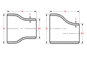
Standard: ANSI B16.9 / 16.28, ASTM A53/A106, API 5L, ASME B36.10M---1996, DIN2605 / 2615 / 2616, JIS P2311/2312
Surface treatment: Transparent oil, rust-proof black oil or hot galvanized.
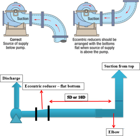
Horizontal liquid reducers are usually eccentric, with a flat top that avoids the accumulation of air bubbles in the system. Eccentric reducers are used on the suction side of pumps to stop air trapping in the tubing. The gradual accumulation of air in a concentric reducer can result in a large bubble, causing the pump to stall or cavitation when drawn into the pump. Horizontal gas reducers are often eccentric with smooth bottoms, allowing condensed water or oil to drain at low stages.
Concentric Reducer vs Eccentric Reducer Differences
Concentric reducers are widely used while eccentric reducers are applied to maintain the top and bottom pipe level. Eccentric Reducers also avoids trapping of air inside the pipe, and Concentric Reducer removes noise pollution.
Manufacturing Process of Steel Pipe Reducer
There are versatile manufacturing processes for the reducers. These are made of welded pipes with the required filling material. However, EFW and ERW pipes cannot use the reducer. To manufacture forged parts, different kinds of methods are used including cold and hot forming processes. It includes the ‘Outer Die Method.’
Outer Dia Method
It is the most common method for manufacturing the steel pipe reducer. The pipe is cut and pressed in the outer die whereas, one end of the pipe is compressed into the smaller size. This method is fit for manufacturing small and medium-size reducers.
Connection Types of Pipe Reducer
Ranges from different connection types, pipe reducer could be classified with socket weld reducer and butt weld reducer.
Socket Weld Reducer vs Butt Weld Reducer
Socket weld reducer also called socket weld insert, it has three types 1, 2 and 3. Manufacturing standards comply to ASME B16.11.
The Socket Weld resists ½ of the strength of butt welding, so it is used for small-diameter pipes possessing a diameter of NPS 2 or less. Butt Weld has good strength, as it is suitable for high pressure and temperature pipelines.
Butt weld reducer ends in plan or beveled, manufactured in accordance with ASME B16.9 and welding process according ASME B16.25.
Butt weld fittings are available in concentric reducers and eccentric reducers to reduce the flow from one size of pipe to another.
The pipe reducer is one of the pipe fittings, which is used for connecting two pipes with varying diameters. A pipe reducer is used to change rate of fluids the flow through. Reducers are usually made by reducing pressing processes, or by expanding pressing processes or by both reducing and expanding pressing processes together, and we can also adopt stamping processes for reducers with some specifications. Reducers are categorized into types, Eccentric and Concentric Reducer. The pipe reducers are widely available in a various materials as per the demands of its applications and industries and also available in different dimensions too.
ASME B16.9 Standard covers overall dimensions, tolerances,ratings, testing, and markings for factory-made wrought buttwelding fittings in sizes NPS 1⁄2 through NPS 48 (DN 15 through DN 1200).
Download PDF| Nominal | Outside Diameter | 90° Elbows | 45° Elbows | 180° Returns | ||||
|---|---|---|---|---|---|---|---|---|
| Pipe Size |
Long Radius | Short Radius | Long Radius | Long Radius | ||||
| (inches) | (mm) | (inches) | Center to Face | Center to Face | Center to Face | Radius | Center to Center | Back to face |
| (inches) | (inches) | (inches) | (inches) | (inches) | (inches) | |||
| 1/2 | 21.3 | 0.84 | 1.5 | – | 5/8 | 2 | 1.875 | |
| 3/4 | 26.7 | 1.05 | 1.125 | – | 7/16 | 2.25 | 1.6875 | |
| 1 | 33.4 | 1.315 | 1.5 | 1 | 7/8 | 3 | 2.1875 | |
| 1.25 | 42.2 | 1.66 | 1.875 | 1.25 | 1 | 3.75 | 2.75 | |
| 1.5 | 48.3 | 1.9 | 2.25 | 1.5 | 1.125 | 3 | 4.5 | 3.25 |
| 2 | 60.3 | 2.375 | 3 | 2 | 1.375 | 4 | 6 | 4.1875 |
| 2.5 | 73 | 2.875 | 3.75 | 2.5 | 1.75 | 5 | 7.5 | 5.1875 |
| 3 | 88.9 | 3.5 | 4.5 | 3 | 2 | 6 | 9 | 6.25 |
| 3.5 | 101.6 | 4 | 5.25 | 3.5 | 2.25 | 7 | 10.5 | 7.25 |
| 4 | 114.3 | 4.5 | 6 | 4 | 2.5 | 8 | 12 | 8.25 |
| 5 | 141.3 | 5.563 | 7.5 | 5 | 3.125 | 10 | 15 | 10.3125 |
| 6 | 168.3 | 6.625 | 9 | 6 | 3.75 | 12 | 18 | 12.3125 |
| 8 | 219.1 | 8.625 | 12 | 8 | 5 | 12 | 24 | 16.3125 |
| 10 | 273.1 | 10.75 | 15 | 10 | 6.25 | 15 | 30 | 20.375 |
| 12 | 323.9 | 12.75 | 18 | 12 | 7.5 | 18 | 36 | 24.375 |
| NOMINAL PIPE SIZE NPS | ANGULARITY TOLERANCES | ANGULARITY TOLERANCES |
|---|---|---|
| Size | Off Angle Q | Off Plane P |
| ½ to 4 | 0.03 | 0.06 |
| 5 to 8 | 0.06 | 0.12 |
| 10 to 12 | 0.09 | 0.19 |
| 14 to 16 | 0.09 | 0.25 |
| 18 to 24 | 0.12 | 0.38 |
| 26 to 30 | 0.19 | 0.38 |
| 32 to 42 | 0.19 | 0.5 |
| 44 to 48 | 0.18 | 0.75 |
All dimensions are given in inches. Tolerances are equal plus and minus except as noted.
The ASME B16.9 pipe fittings can be used under the jurisdiction of the ASME Boiler & Pressure Vessel Code (BPVC) as well as the ASME Code for pressure piping. Referencing pressure ratings of flanges per ASME B16.5, they can be designated as Classes 150, 300, 600, 900, 1500 and 2500. The allowable pressure ratings for ASME B16.9 pipe fittings may be calculated as for straight seamless pipe of equivalent material in accordance with the rules established in the applicable sections of ASME B31 Code for pressure piping.
The design of butt welding pipe fittings made to ASME B16.9 shall be established by one of the following methods: (a) mathematical analyses contained in pressure vessel or piping codes; (b) proof testing; (c) experimental stress analysis with hydrostatic testing to validate experimental results; (d) detailed stress analysis with results evaluation.
Generally, ASME B16.9 pipe fittings shall be marked to show the following details: “trademark + material grade + wall thickness + size + heat number”. For example, “M ASTM A234 WP5 SCH80 6″ 385“. When steel stamps are used, care shall be taken so that
the marking is not deep enough or sharp enough to cause cracks or to reduce the wall thickness of the fitting below the minimum allowed.
The ASME B16.9 fittings may be made from an extensive range of mateirals covering (1) carbon and low-alloy steels in accordance with ASTM A234 and ASTM A420; (2) austenitic and duplex stainless steels in accordance with ASTM A403 and ASTM A815; (3) nickel alloys in accordance with ASTM B366; (4) aluminum alloys in accordance with ASTM B361; and (5) titanium alloys in accordance with ASTM B363.
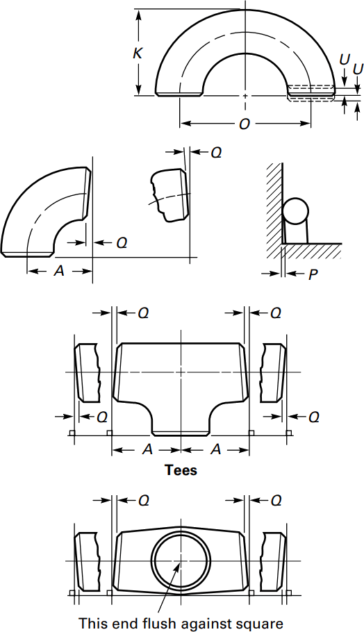
Sizes 1/2″ – 48″
A steel pipe reducer is a component used in the pipelines to reduce its size from large to small bore in accordance to the inner diameter.
The length of the reduction here is equal to an average of the smaller and larger pipe diameters. Here, the reducer can be used as a diffuser or a nozzle. The reducer helps in meeting the existing piping of varied sizes or hydraulic flow of the piping systems. The usage of a steel reducer is carried out in the chemical factories and power plants. It makes the piping system reliable and compact. It safeguards the piping system from any kind of adverse impact or thermal deformation. When it is on the pressure circle, it prevents from any type of leakage and is easy to install. The nickel or chrome coated reducers extends the product life, useful for high vapor lines, and prevents corrosion.
Pipe fitting dimensions are in either metric or Standard English.
Because pipe fitting covers Pipe Fitting Dimensions several aspects, only the most common pipe fitting sizes can be given here. The most applied version is the 90° long radius and the 45° elbow, while the 90° short radius elbow is applied if there is too little space. The function of a 180° elbow is to change direction of flow through 180°. Both, the LR and the SR types have a center to center dimension double the matching 90° elbows. These fittings will generally be used in furnesses or other heating or cooling units.
Some of the standards that apply to buttwelded fittings are listed below. Many organizations such as ASME, ASTM, ISO, MSS, etc. have very well developed standards and specifications for buttwelded fittings. It is always up to the designer to ensure that they are following the applicable standard and company specification, if available, during the design process.
Some widely used pipe fitting standards are as follows:
ASME: American Society for Mechanical Engineers
This is one of the reputed organizations in the world developing codes and standards.
The schedule number for pipe fitting starts from ASME/ANSI B16. The various classifications of ASME/ANSI B16 standards for different pipe fittings are as follows:
ASTM International: American Society for Testing and Materials
This is one of the largest voluntary standards development organizations in the world. It was originally known as the American Society for Testing and Materials (ASTM).
AWWA: American Water Works Association
AWWA About – Established in 1881, the American Water Works Association is the largest nonprofit, scientific and educational association dedicated to managing and treating water, the world’s most important resource.
ANSI: The American National Standards Institute
ANSI is a private, non-profit organization. Its main function is to administer and coordinate the U.S. voluntary standardization and conformity assessment system. It provides a forum for development of American national standards. ANSI assigns “schedule numbers”. These numbers classify wall thicknesses for different pressure uses.
MSS STANDARDS: Manufacturers Standardization Society
The Manufacturers Standardization Society (MSS) of the Valve and Fittings Industry is a non-profit technical association organized for development and improvement of industry, national and international codes and standards for: Valves, Valve Actuators, Valve Modification, Pipe Fittings, Pipe Hangers, Pipe Supports, Flanges and Associated Seals
Difference between “Standard” and “Codes”:
Piping codes imply the requirements of design, fabrication, use of materials, tests and inspection of various pipe and piping system. It has a limited jurisdiction defined by the code. On the other hand, piping standards imply application design and construction rules and requirements for pipe fittings like adapters, flanges, sleeves, elbows, union, tees, valves etc. Like a code, it also has a limited scope defined by the standard.
Factors affecting standards: “Standards” on pipe fittings are based on certain factors like as follows:
BSP: British Standard Pipe
BSP is the U.K. standard for pipe fittings. This refers to a family of standard screw thread types for interconnecting and sealing pipe ends by mating an external (male) with an internal (female) thread. This has been adopted internationally. It is also known as British Standard Pipe Taper threads (BSPT )or British Standard Pipe Parallel (Straight) threads (BSPP ). While the BSPT achieves pressure tight joints by the threads alone, the BSPP requires a sealing ring.
JIS: Japanese Industrial Standards
This is the Japanese industrial standards or the standards used for industrial activities in Japan for pipe, tube and fittings and published through Japanese Standards Associations.
NPT: National Pipe Thread
National Pipe Thread is a U.S. standard straight (NPS) threads or for tapered (NPT) threads. This is the most popular US standard for pipe fittings. NPT fittings are based on the internal diameter (ID) of the pipe fitting.
BOLTS & NUTS
We are manufacturer of Flange bolts & Nuts and supply high quality
AN: Here, “A” stands for Army and “N” stands for Navy
The AN standard was originally designed for the U.S. Military. Whenever, a pipe fitting is AN fittings, it means that the fittings are measured on the outside diameter of the fittings, that is, in 1/16 inch increments.
For example, an AN 4 fitting means a fitting with an external diameter of approximately 4/16″ or ¼”. It is to be noted that approximation is important because AN external diameter is not a direct fit with an equivalent NPT thread.
Dash (-) size
Dash size is the standard used to refer to the inside diameter of a hose. This indicates the size by a two digit number which represents the relative ID in sixteenths of an inch. This is also used interchangeably with AN fittings. For example, a Dash “8” fitting means an AN 8 fitting.
ISO: International Organization for Standardization
ISO is the industrial pipe, tube and fittings standards and specifications from the International Organization for Standardization. ISO standards are numbered. They have format as follows:
“ISO[/IEC] [IS] nnnnn[:yyyy] Title” where
| Standard | Specification |
|---|---|
| ASTM A234 | Standard Specification for Piping Fittings of Wrought Carbon Steel and Alloy Steel for Moderate and High Temperature Service |
| ASTM A420 | Standard Specification for Piping Fittings of Wrought Carbon Steel and Alloy Steel for Low-Temperature Service |
| ASTM A234 WPB | ASTM A234 WPB refers to a specific grade of carbon steel pipe fittings, which are widely used in pressure piping and pressure vessel fabrication for service at moderate and elevated temperatures. |
| ASME B16.9 | ASME B16.9 Standard covers overall dimensions, tolerances,ratings, testing, and markings for factory-made wrought buttwelding fittings in sizes NPS 1⁄2 through NPS 48 (DN 15 through DN 1200). |
| ASME B16.28 | ASME B16.28 Standard covers ratings, overall dimensions, testing, tolerances, and markings for wrought carbon and alloy steel buttwelding short radius elbows and returns. |
| MSS SP-97 | MSS SP-97 Standard Practice covers essential dimensions, finish, tolerances, testing, marking, material, and minimum strength requirements for 90 degree integrally reinforced forged branch outlet fittings of buttwelding, socket welding, and threaded types. |
| ASTM A403 | Standard Specification for Wrought Austenitic Stainless Steel Piping Fittings. |
| DIN | EN | ASME |
|---|---|---|
| St 35.8 I St 35.8 III 15 Mo 3 13 CrMo 4 4 10 CrMo 9 10 St 35 N St 52.0 St 52.4 |
P235GH-TC1 P235GH-TC2 16Mo3 13CrMo4-5 10CrMo9-10 X10CrMoVNb9-1 P215NL P265NL L360NB L360NE P355N P355NL1 P355NH |
WPB WPL6 WPL3 WPHY 52 WP11 WP22 WP5 WP9 WP91 WP92 |
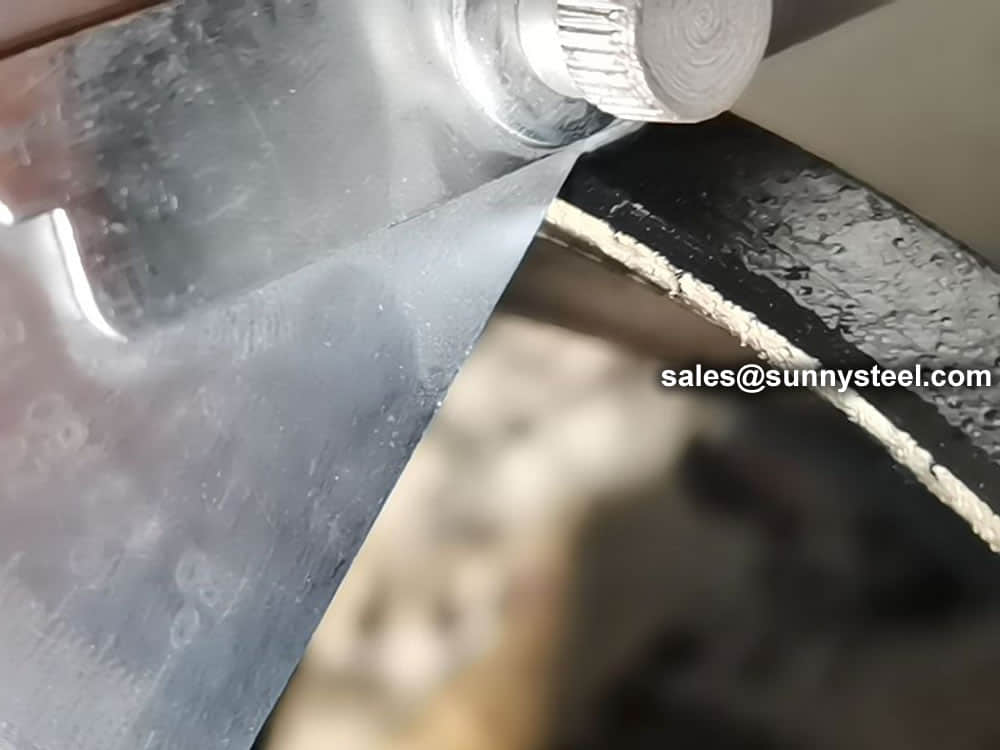
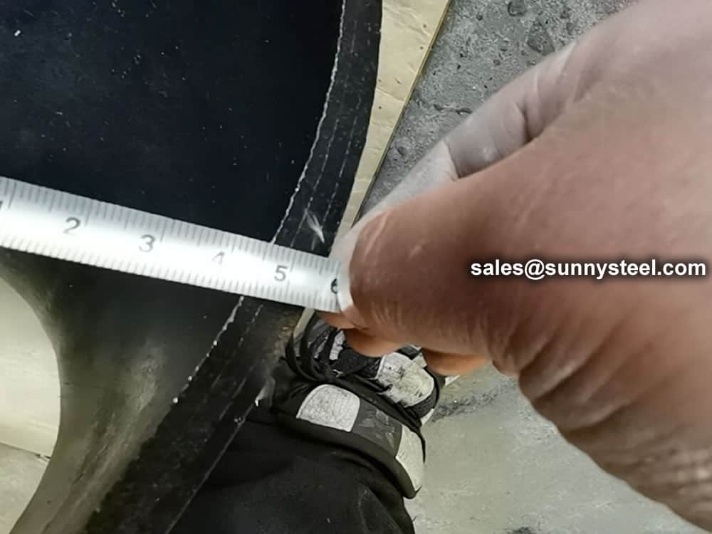
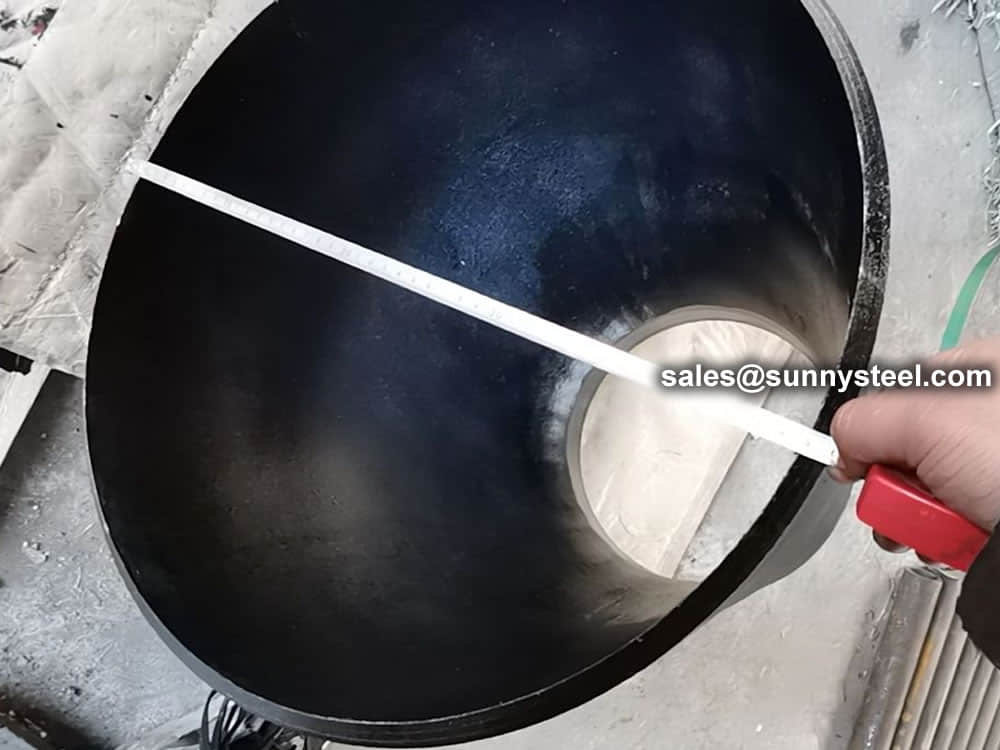
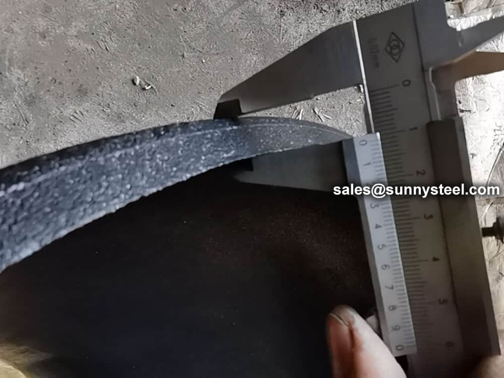
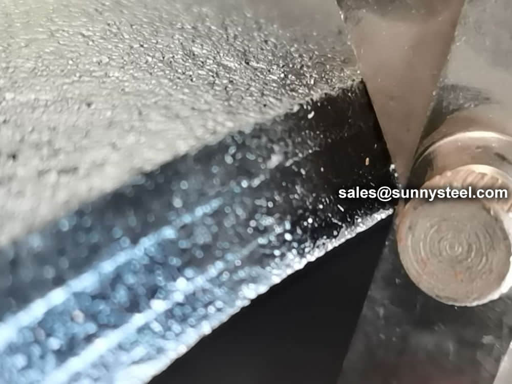
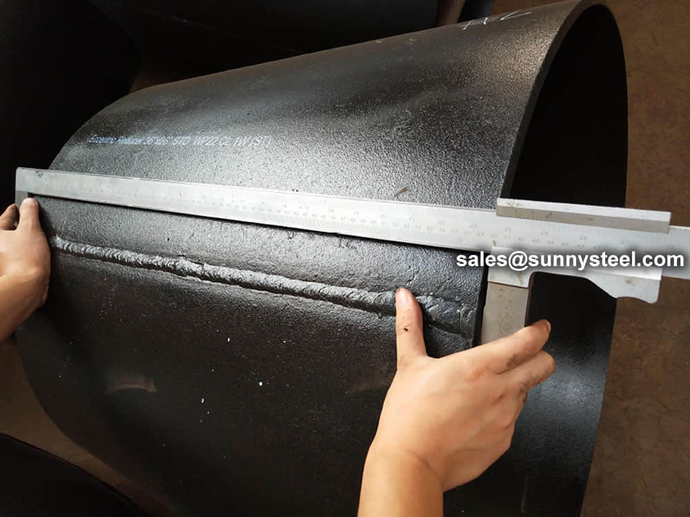
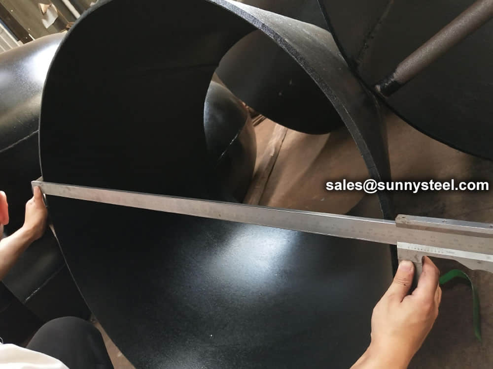
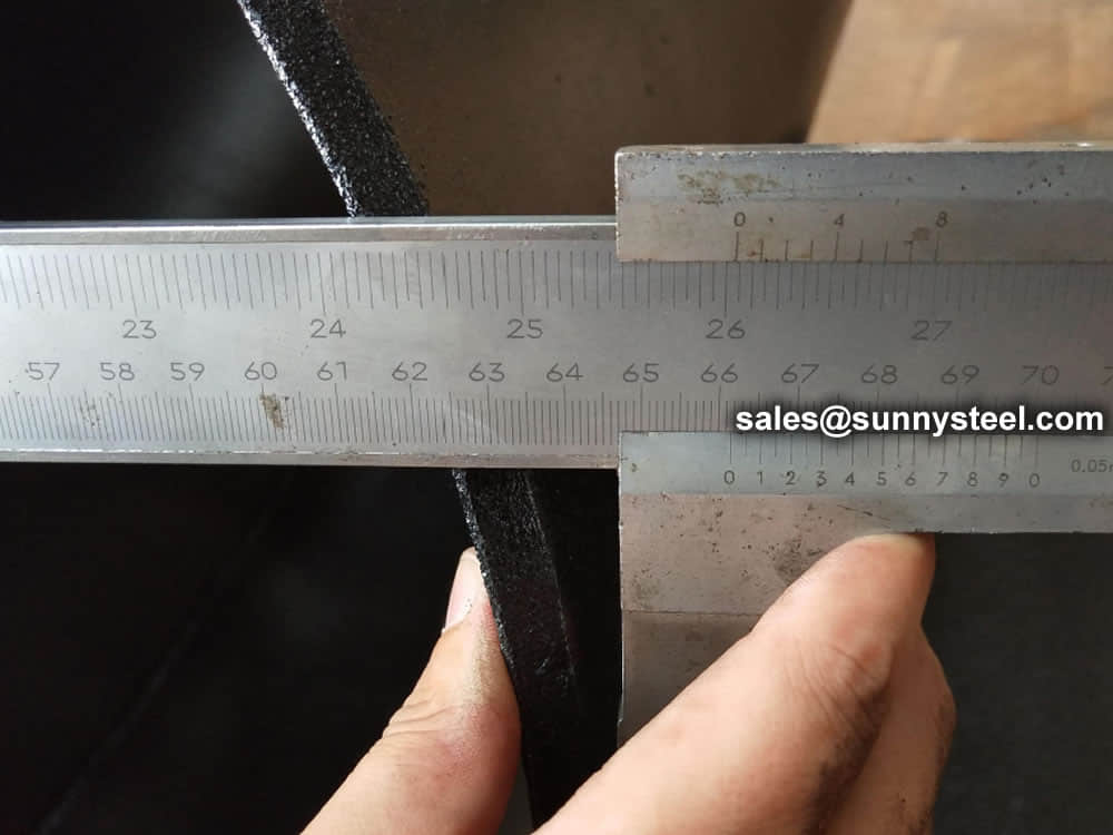
Visual Inspection is conducted on fittings to check any surface imperfections. Both fittings body and weld are checked for any visible surface imperfections such as dents, die marks, porosity, undercuts, etc. Acceptance as per applicable standard.
For packing of carbon steel flanges with painting,we would use the bubble wrap to protect the painting.For flanges without painting or oiled with long-term shipment,we would suggest client to use the anti-tarnish paper and plastic bag to prevent the rust.
